Run a minimalistic program written in assembler on STM32-H103 development board
Introduction
The goal of this article is to write a minimalistic program in ARM assembler and prove that it runs correctly on a STM32-H103 development board.
Hardware equipment:
-
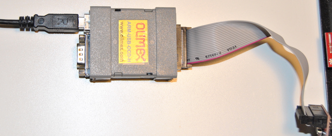
An ARM-USB-OCD-H JTAG adapter from Olimex
-
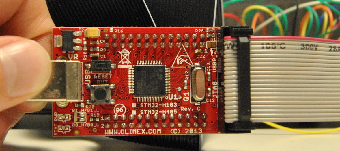
A STM32-H103 development board with an ARM Cortex M3 (STM32F103RBT6)
Software tools:
-
The following tools that are part of GNU Binutils:
-
GNU Assembler (gas) for compiling
-
GNU Linker (ld) for linking
-
GNU objcopy for converting from elf format to binary format
-
GNU objdump for inspecting the output from GNU Assembler and GNU Linker
-
GNU nm for listing symbols in object files, i.e. the output from GNU Assembler
-
-
OpenOCD for flashing
Cross compiler
We will use the PC to ARM bare metal cross compiler version of the GNU tool chain specified in the previous section. This means that we will run the tools on a PC running Linux but compile them to run on an ARM Cortex-M3 processor without any operating system on it.
The name of the cross compiler tools inlcude arm-none-eabi, the name of the GNU Assembler is arm-none-eabi-as for example. I think this means:
arm- ARM is the target of the cross compilationnone- the target is running bare metal, i.e. without operating systemeabi- embedded applicaton binary interface
Links:
- GNU ARM Ebedded Toolchain at the ARM Developer site
How to install GNU binutils for ARM
sudo apt-get install binutils-arm-none-eabi
Assembler code
First step is to write our program in assembler.
The program shall:
- Store value
3in register 2. - Store value
4in register 3. - Add register 2 and register 3, store result in register 4.
    .thumb
    .section    isr_vector
    .word       0
    .word       _start + 1
    .word       _nmi_handler + 1
    .word       _hard_fault + 1
    .word       _memory_fault + 1
    .word       _bus_fault + 1
    .word       _usage_fault + 1
    .text
    .global _start
_start:
    mov r2, #3
    mov r3, #4
    add r4, r2, r3

stop:
    b stop

_dummy:
_nmi_handler:
_hard_fault:
_memory_fault:
_bus_fault:
_usage_fault:
    add r0, #1
    add r1, #1
    b _dummy
The program is written using the Thumb instruction set which is the intruction set supported by ARM Cortex-M3 CPUs, see chapter 3 in the STM32F10xxx Programming Manual. Let’s go through our program starting from the top.
.thumb is an ARM assembler directive identical to ARM assembler directive .code 16. .code 16 selects the Thumb instruction set. An assembler directive begins with a dot ., it will not generate a machine language instruction. See section 3.5 Sections in the gas documentation.
.section isr_vector will put the code that follows in a section named isr_vector. See section 7.78 .section name in the gas documentation. We will use sections in the linker step later to get our code in the correct order in the final output file.
The .word directive is used to enter data into the output file. The processor on the STM32-H103 development board is a STM32F103RBT6 from STMicroelectronics. It uses 32-bit words. See section 2.1.5 Data types in the STM32F10xxx Programming Manual.
We use the .word directive to set the reset vector of the microcontroller. The reset vector of STM32F103RBT6 is defined in section 2.3.4 in the STM32F10xxx Programming Manual, it defines the start addresses for different types of exceptions. One important example is what happens at system reset. The start address of the code is read from address 0x0000 0004. The least-significant bits of each start-address in the vector must be 1, this indicates that the exception handlers are implemented with Thumb code. The first 7 entries in the reset vector is listed below. The first entry is not a start address, instead it sets the initial value of the stack pointer. We will set it to 0 since we don’t make use of the stack. The stack pointer is mandatory to initialize when compiling C code.
Address        Description
=======        ===========
0x0000 0000    Initial Stack Pointer (SP) value
0x0000 0004    Reset exception
0x0000 0008    NMI
0x0000 000C    Hard fault
0x0000 0010    Memory management fault
0x0000 0014    Bus fault
0x0000 0018    Usage fault
The GNU Linker (arm-eabi-none-ld) will assume that the entry point is defined with a symbol named _start. The entry point is the where the first instruction to execute in the program is located. We define this symbol with _start: but we also have to make it visible to the linker using the .global directive. See section 7.36 in the GNU Linker documentation.
The mov instruction copies the value of the operand into a register. mov r2, #3 will move decimal value 3 into register 2. The operand can be a constant or a register. See section 3.3.3 Flexible second operand in STM32F10xxx Programming Manual.
The add instruction adds the r2 and r3 values and stores them in r4.
stop: defines the label stop. A label is a symbol that represents the current value of the location counter. See section 5.1 in the GNU Assembler documentation.
The b instruction means branch. The Program Counter will jump to the the location of the stop label in the code. The purpose is to have an infinite loop after our program ends.
We implement one common handler for the non-reset exceptions. We do this by defining multiple labels in one place.
_dummy:
_nmi_handler:
_hard_fault:
_memory_fault:
_bus_fault:
_usage_fault:
We increase registers r0 and r1 with one in an infinite loop if the common handler. We can inspect the value of r0 and r1 when running the program to detect that a fault has occurred.
How to compile the assembler code
We use the GNU Assembler to compile our assembler code. The input file is named add.s and the output is add.o.
arm-none-eabi-as -o add.o add.s
How to inspect assembler output with objdump
The assembler output file add.o is the object file. We can inspect the object file using the GNU objdump tool.
The --disassemble, -d option will show the assembler mnemonics for the machine instructions in the object file. This can be interested when compiling a C file. In our case we should get exactly the program we have written in assembler.
$ arm-none-eabi-objdump --disassemble add.o

add.o:     file format elf32-littlearm


Disassembly of section .text:

00000000 <_start>:
   0:   2203        movs    r2, #3
   2:   2304        movs    r3, #4
   4:   18d4        adds    r4, r2, r3

00000006 <stop>:
   6:   e7fe        b.n 6 <stop>

00000008 <_bus_fault>:
   8:   3001        adds    r0, #1
   a:   3101        adds    r1, #1
   c:   e7fc        b.n 8 <_bus_fault>
The --syms, -t option will print the symbol table of the file. This is similar to what the nm tool provides.
$ arm-none-eabi-objdump --syms add.o

add.o:     file format elf32-littlearm

SYMBOL TABLE:
00000000 l    d  .text  00000000 .text
00000000 l    d  .data  00000000 .data
00000000 l    d  .bss   00000000 .bss
00000000 l    d  isr_vector 00000000 isr_vector
00000008 l       .text  00000000 _nmi_handler
00000008 l       .text  00000000 _hard_fault
00000008 l       .text  00000000 _memory_fault
00000008 l       .text  00000000 _bus_fault
00000008 l       .text  00000000 _usage_fault
00000006 l       .text  00000000 stop
00000008 l       .text  00000000 _dummy
00000000 l    d  .ARM.attributes    00000000 .ARM.attributes
00000000 g       .text  00000000 _start
The first line in the symbol table is:
00000000 l d .text 00000000 .text
It should be interpreted like this:
00000000is the symbol value (the address)lmeans that it is a local symboldmeans that it is a debugging symbol.textis the section the symbol is associated with. A*UND*here would mean that the section is not defined in the current object file.00000000is the alignment for common symbols and size for other symbols. I am not sure of the definition of common symbol, but I think it means symbols used in multiple object files..textis the symbol name
Another line in the symbol table is:
00000000 g .text 00000000 _start
It should be interpreted like this:
00000000is the symbol value (the address)gmeans that it is a global symbol(space)instead ofdmeans that it is a normal symbol.textis the section the symbol is associated with.00000000is the alignment for common symbols and size for other symbols._startis the symbol name
How to print symbol table in the object file using the nm tool
We can use the GNU nm tool to list the symbols in the object file.
$ arm-none-eabi-nm add.o
00000008 t _bus_fault
00000008 t _dummy
00000008 t _hard_fault
00000008 t _memory_fault
00000008 t _nmi_handler
00000000 T _start
00000006 t stop
00000008 t _usage_fault
The first column is symbol value.
The second column shows the symbol type. Lowercase means that the symbol is local. Uppercase means that the symbol is global. Symbol type t, T means that the symbol is in the text (code) section.
The third and last column shows the symbol name.
Linker script
The linker script will tell the linker on what memory locations to put different sections of the code. See chapter 3 about Linker Scripts in the GNU Linker documentation. We have the isr_vector and .text sections in our program.
SECTIONS
{
    .  = 0x0;         /* From 0x00000000 */
    .text :
    {
        *(isr_vector) /* Interrupt Service Routine Vector table */
        *(.text)      /* Program code */
    }
}
SECTIONS is a command that describes the memory layout of the output file. See section 3.3 Simple Linker Script Example and section 3.6 SECTIONS Command in the GNU Linker documentation.
Within the SECTIONS command we do the following.
- The location counter denoted by a dot
.is set to 0. - The input sections
isr_vectorand.textshall be put in the.textoutput section.*(isr_vector)means that we should pickisr_vectorfrom all input files. In our case we only have one input file, i.e.add.o. The location (memory address) of the start of the.textoutput section will be 0x0 since this is the value of the location counter upon defining the.textsection.
How to run the linker
The input to the linker is add.o and linker script stm32.ld. The output is add.elf which is in elf format.
arm-none-eabi-ld -Tstm32.ld -o add.elf add.o
The -T option tells the linker to replace the default linker script with our custom made stm32.ld. See section 2.1 Command Line Options in the GNU Linker documentation.
How to inspect linker output with objdump and nm
We can inspect the linker output, i.e. add.elf, with GNU objdump and GNU nm. Similar to what we did with the object file (add.o) above.
Let’s disassemble with objdump first.
$ arm-none-eabi-objdump --disassemble add.elf

add.elf:     file format elf32-littlearm


Disassembly of section .text:

00000000 <_start-0x1c>:
   0:   00000000    .word   0x00000000
   4:   0000001d    .word   0x0000001d
   8:   00000025    .word   0x00000025
   c:   00000025    .word   0x00000025
  10:   00000025    .word   0x00000025
  14:   00000025    .word   0x00000025
  18:   00000025    .word   0x00000025

0000001c <_start>:
  1c:   2203        movs    r2, #3
  1e:   2304        movs    r3, #4
  20:   18d4        adds    r4, r2, r3

00000022 <stop>:
  22:   e7fe        b.n 22 <stop>

00000024 <_bus_fault>:
  24:   3001        adds    r0, #1
  26:   3101        adds    r1, #1
  28:   e7fc        b.n 24 <_bus_fault>
Next we can inspect the symbol table with nm.
$ arm-none-eabi-nm add.elf
00000024 t _bus_fault
00000024 t _dummy
00000024 t _hard_fault
00000024 t _memory_fault
00000024 t _nmi_handler
0000001c T _start
00000022 t stop
00000024 t _usage_fault
We can have the symbols sorted numerically by their addresses using the --numeric-sort, -v option.
$ arm-none-eabi-nm --numeric-sort add.elf
0000001c T _start
00000022 t stop
00000024 t _bus_fault
00000024 t _dummy
00000024 t _hard_fault
00000024 t _memory_fault
00000024 t _nmi_handler
00000024 t _usage_fault
Convert from elf to binary
The output format from the linker is elf. We can convert from elf to binary using GNU objcopy.
$ arm-none-eabi-objcopy -O binary add.elf add.bin
Makefile
Now we can create a makefile with all the build commands.
all: add.s stm32.ld clean
    @echo "Running target all"
    arm-none-eabi-as -o add.o add.s
    arm-none-eabi-ld -Tstm32.ld -o add.elf add.o
    arm-none-eabi-objcopy -O binary add.elf add.bin

print_symbols: all
    @echo "Running target print_symbols"
    arm-none-eabi-nm --numeric-sort add.elf

clean:
    @echo "Running target clean"
    rm -f *.o
    rm -f *.elf
    rm -f *.bin
OpenOCD
See Using OpenOCD to flash ARM Cortex M3 for information on how to flash.
Flash add.bin and run it
-
Start the openocd server in one command window
$ openocd -f openocd.cfg -
Connect to the openocd server using telnet in another command window
$ telnet localhost 4444 -
Halt execution of target in case it is running
halt -
Erase content on flash
stm32f1x mass_erase 0 -
Flash add.bin
flash write_bank 0 add.bin 0 -
Run program
reset run -
Verify that
r2is set to 3,r3to 4 andr4to 7halt reg
Run program again after setting register values manually to zeros
-
Run the add.bin program according to previous section
-
Halt execution in the infinite loop at address 0x00000022
> halt tm32f1x.cpu: target state: halted target halted due to debug-request, current mode: Thread xPSR: 0x01000000 pc: 0x00000022 msp: 00000000 -
Set register values
reg 2 0 reg 3 0 reg 4 0 -
Resume execution to let register values be set
resume -
Halt execution again and checkt that r2, r3 and r4 are all zeros
halt reg -
Run the program again
reset run -
Halt execution
halt -
Verify that
r2is set to 3,r3to 4 andr4to 7reg ==== arm v7m registers (0) r0 (/32): 0x00000020 (1) r1 (/32): 0x00000000 (2) r2 (/32): 0x00000003 (3) r3 (/32): 0x00000004 (4) r4 (/32): 0x00000007 (5) r5 (/32): 0x2000006E (6) r6 (/32): 0x00000020 (7) r7 (/32): 0x00000014 (8) r8 (/32): 0x37FEFFFE (9) r9 (/32): 0xFFEDFFFC (10) r10 (/32): 0xB3AA944C (11) r11 (/32): 0x88CAD384 (12) r12 (/32): 0xFBF8FFFF (13) sp (/32): 0x00000000 (14) lr (/32): 0xFFFFFFFF (15) pc (/32): 0x00000022 (16) xPSR (/32): 0x01000000 (17) msp (/32): 0x00000000 (18) psp (/32): 0xD080DE44 (19) primask (/1): 0x00 (20) basepri (/8): 0x00 (21) faultmask (/1): 0x00 (22) control (/2): 0x00 -
We have proven that our minimalistic program runs correctly by inspecting the register values.
References
I have linked to the STM32F10xxx Programming Manual several times in this article.
Links
I made use of the following articles while writing this article in addition to the GNU binutils documentaiton I have linked to above:
- http://www.bravegnu.org/gnu-eprog/index.html
- http://www.coranac.com/tonc/text/asm.htm
- http://dbp-consulting.com/tutorials/debugging/basicAsmDebuggingGDB.html
- http://pygmy.utoh.org/riscy/cortex/led-stm32.html
- https://www.community.arm.com/processors/b/documents/posts/writing-your-own-startup-code-for-cortex-m
- http://www.cse.unsw.edu.au/~cs3221/labs/assembler-intro.pdf
- http://eleceng.dit.ie/frank/arm/BareMetalSTM32F0Discovery/blinky.html
- http://stackoverflow.com/questions/11785973/converting-very-simple-arm-instructions-to-binary-hex#11786481