Run a C program bare metal on an ARM Cortex M3
Edit 2018-08-17: Add section “Files”
Contents
- Introduction
- Files
- Hardware equipment
- Software tools
- C program
- ARM assembler code
- ARM Cortex M3 memory map
- ARM Cortex M3 boot sequence
- Stack pointer
- C prerequisites
- Building
- Running
Introduction
The goal of this article is to run a C program bare metal on an ARM Cortex M3. We will go through the assembler code generated from a small program written in C and come up with the prerequisites that must be in place in order for it to run.
Files
The following files are used in this article:
I use the following makefile to compile and link:
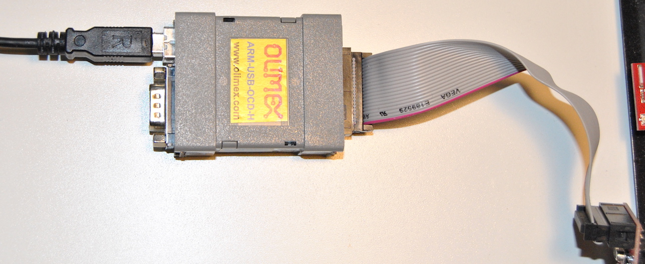
Hardware equipment
-
An ARM-USB-OCD-H JTAG adapter from Olimex
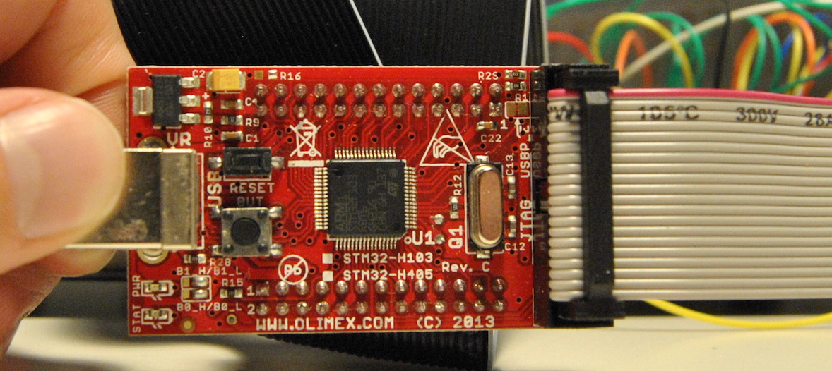
-
A STM32-H103 development board with an ARM Cortex M3 (STM32F103RBT6)
Software tools
-
The following tools that are part of GNU Binutils:
-
GNU Linker (ld) for linking
-
GNU objcopy for converting from elf format to binary format
-
GNU objdump for inspecting the output from GNU GCC and GNU Linker
-
The cross compiler versions of these tools can be obtained as Ubuntu 18.04 packages.
sudo apt-get install binutils-arm-none-eabisudo apt-get install gcc-arm-none-eabisudo apt-get install gdb-multiarchARM also maintains a GNU Embedded Toolchain for Arm which is available for download at https://developer.arm.com/open-source/gnu-toolchain/gnu-rm/downloads.
I use the Ubuntu package variants in this article with the following versions:
$ gdb-multiarch --version | head -n1
GNU gdb (Ubuntu 8.1-0ubuntu3) 8.1.0.20180409-git

$ arm-none-eabi-gcc --version | head -n1
arm-none-eabi-gcc (15:6.3.1+svn253039-1build1) 6.3.1 20170620

$ arm-none-eabi-ld --version | head -n1
GNU ld (2.27-9ubuntu1+9) 2.27

$ arm-none-eabi-objcopy --version | head -n1
GNU objcopy (2.27-9ubuntu1+9) 2.27

$ arm-none-eabi-objdump --version | head -n1
GNU objdump (2.27-9ubuntu1+9) 2.27
C program
Below is our C program. It defines variables a, b and stores their sum in a variable named sum.
static const int a = 7;
static int b = 8;
static int sum;

void main()
{
  sum = a + b;
}
ARM assembler code
We compile the program using the -S command line option:
arm-none-eabi-gcc -S -mcpu=cortex-m3 -mthumb test_program.cThe -S option will give us the corresponding assembler code, see section 3.2 in the gcc documenation:
-S
    Stop after the stage of compilation proper; do not assemble.
    The output is in the form of an assembler code file for each
    non-assembler input file specified.

    By default, the assembler file name for a source file is made
    by replacing the suffix ‘.c’, ‘.i’, etc., with ‘.s’.

    Input files that don't require compilation are ignored.
The full assembler code listing of test_program.s is shown below. We will divide it into parts and analyze.
    .cpu cortex-m3
    .eabi_attribute 20, 1
    .eabi_attribute 21, 1
    .eabi_attribute 23, 3
    .eabi_attribute 24, 1
    .eabi_attribute 25, 1
    .eabi_attribute 26, 1
    .eabi_attribute 30, 6
    .eabi_attribute 34, 1
    .eabi_attribute 18, 4
    .file "test_program.c"
    .section  .rodata
    .align  2
    .type a, %object
    .size a, 4
a:
    .word 7
    .data
    .align  2
    .type b, %object
    .size b, 4
b:
    .word 8
    .bss
    .align  2
sum:
    .space  4
    .size sum, 4
    .text
    .align  1
    .global main
    .syntax unified
    .thumb
    .thumb_func
    .fpu softvfp
    .type main, %function
main:
    @ args = 0, pretend = 0, frame = 0
    @ frame_needed = 1, uses_anonymous_args = 0
    @ link register save eliminated.
    push  {r7}
    add r7, sp, #0
    movs  r2, #7
    ldr r3, .L2
    ldr r3, [r3]
    add r3, r3, r2
    ldr r2, .L2+4
    str r3, [r2]
    nop
    mov sp, r7
    @ sp needed
    pop {r7}
    bx  lr
.L3:
    .align  2
.L2:
    .word b
    .word sum
    .size main, .-main
    .ident  "GCC: (15:6.3.1+svn253039-1build1) 6.3.1 20170620"
ARM assembly attributes
The first part defines ARM assembly attributes which do not correspond to any specific line of code.
    .cpu cortex-m3
    .eabi_attribute 20, 1
    .eabi_attribute 21, 1
    .eabi_attribute 23, 3
    .eabi_attribute 24, 1
    .eabi_attribute 25, 1
    .eabi_attribute 26, 1
    .eabi_attribute 30, 6
    .eabi_attribute 34, 1
    .eabi_attribute 18, 4
    .file "test_program.c"
ARM specific directives:
-
The
.cpu cortex-m3directive sets the target processor. Valid names are the same as for the-mcpucommand line option. See GNU Assembler (as) ARM command line options -
The
.eabi_attributesets the EABI object attribute tag to value. It is unclear for me what this means. A list of valid tags are available in the GNU Assembler (gas) documentation.
General directives:
- The
.filedirective tells the GNU Assembler (as) that we are about to start a new file. See section 7.32 in the GNU Assembler (gas) documentation.
Variable a
C code
static const int a = 7;Assembler code
    .section  .rodata
    .align  2
    .type a, %object
    .size a, 4
a:
.word 7- The
.sectiondirective puts variableain therodatasection since it is declared usingconst. - The
.align <alignment>directive pads the locations counter to an absolute alignment storage boundary. For ARM the alignment argument specifies “the number of low-order zero bits the location counter must have after advancement”..align 2advances the location counter until it is a multiple of 4. - The
.typedirective tells GNU Assembler (as) ifais a function symbol or an object symbol. In this caseais an object symbol. See GNU Assembler (as) .type directive. - The
.size <name>, <expression>directive sets the size of symbol<name>. The size is specified by<expression>. See GNU Assembler (as) .size directive. - Label
a“represents the current value of the active location counter”. See GNU Assembler (as) Labels”. - The
.worddirective stores the value7at the current location.
Variable b
C code
static int b = 8;Assembler code
    .data
    .align  2
    .type b, %object
    .size b, 4
b:
.word 8- Variable
bis put in thedatasection instead of in the.rodatasection as variableais. The.datadirective “tells as to assemble the following statements onto the end of the data section”. See GNU Assembler (as) .data directive. - The other directives used by
bare identical to the ones used bya.
Variable sum
C code
static int sum;Assembler code
    .bss
    .align  2
sum:
    .space  4
.size sum, 4- The
sumvariable is put in the.bsssection since it is uninitialized. - The
.space <size>, <fill>directive fills<size>bytes with the value specified with<fill>. 0 is assumed if<fill>is omitted. See GNU Assembler (as) .space directive.
Start of main() function
C code
void main()
{
Assembler code
    .text
    .align  1
    .global main
    .syntax unified
    .thumb
    .thumb_func
    .fpu softvfp
    .type main, %function
main:
    @ args = 0, pretend = 0, frame = 0
    @ frame_needed = 1, uses_anonymous_args = 0
    @ link register save eliminated.
    push  {r7}
add r7, sp, #0-
The
.text <subsection>directive “tells as to assemble the following statements onto the end of the text<subsection>”. Subsection zero will be used by default if not specified. See GNU Assembler (as) .text directive. -
The
.align <alignment>directive pads the locations counter to an absolute alignment storage boundary. For ARM the alignment argument specifies “the number of low-order zero bits the location counter must have after advancement”..align 2advances the location counter until it is a multiple of 4. See GNU Assembler (as) .align directive. -
The
.globaldirective makes the symbol available to other c files that our file is linked with. See GNU Assembler (as) .global directive. -
The
.syntax unifieddirective changes some details regarding how the ARM instruction set is intepreted.unifiedis the more modern option. See GNU Assembler (as) ARM directives -
The
.thumbdirective is identical to.code 16which means that we will use the Thumb instruction set and not the ARM instruction set. See section 3 in STM32F10xxx Programming Manual. -
The
.thumb_funcdirective “specifies that the following symbol is the name of a Thumb encoded function. This information is necessary in order to allow the assembler and linker to generate correct code for interworking between Arm and Thumb instructions and should be used even if interworking is not going to be performed. The presence of this directive also implies.thumb”. See GNU Assembler (as) ARM Directives. -
The
.fpu softvfpdirective sets floating-point unit. Valid names are the same as for the-mfpucommand line option. See GNU Assembler (as) ARM command line options -
The
.typedirective tells GNU Assembler (as) ifmainis a function symbol or an object symbol. In this casemainis a function symbol. See GNU Assembler (as) .type directive. -
main:is a label and “represents the current value of the active location counter, and is, for example, a suitable instruction operand”. See GNU Assembler (as) Section 5.1 Label. -
Lines starting with
@are comments -
push {r7}pushes registerr7onto the stack. See section 3.4.7 in STM32F10xxx Programming Manual. -
add r7, sp, #0adds the value in registerspwith zero and stores the result in registerr7. So basically we take the memory address stored inspand copies to registerr7I think.
In my understanding the so called frame pointer is stored in register r7. The frame pointer keeps track of where to restore the stack pointer when returning from a function. See Call stack at Wikipedia. So at the beginning of main() we store the current value of frame pointer onto the stack. After that we store the current value of the stack pointer in register r7. This value in r7 shows what value sp shall be restored to when returning from the main() function.
Variable assignment in main() function
C code
sum = a + b;Assembler code
    movs  r2, #7
    ldr r3, .L2
    ldr r3, [r3]
    add r3, r3, r2
    ldr r2, .L2+4
    str r3, [r2]
movs r2, #7copies the value7into registerr2. See section 3.5.6 in STM32F10xxx Programming Manual.-
ldr r3, .L2loads the memory address of variablebinto registerr3. See section 3.4.5 in STM32F10xxx Programming Manual..L2is defined at the end of the assembler code:.L2: .word b .word sum .size main, .-main .ident "GCC: (15:6.3.1+svn253039-1build1) 6.3.1 20170620" ldr r3, [r3]loads registerr3with the current value of variableb. See section 3.4.2 in STM32F10xxx Programming Manual.add r3, r3, r2adds the value of registerr3(variableb) andr2(variablea) and stores the result in registerr3. See section 3.5.1 in STM32F10xxx Programming Manual.ldr r2, .L2+4loads the memory address of variablesuminto registerr2.str r3, [r2]stores the value in registerr3into the memory address of thesumvariable. See section 3.4.4 in STM32F10xxx Programming Manual.
End of main() function
C code
}Assembler code
nop
mov sp, r7
@ sp needed
pop {r7}
bx lrmov sp, r7- At the end of themain()function we copy the memory address stored in the frame pointer (registerr7) back to the stack pointer.pop {r7}pops a value from the stack and stores in registerr7. See section 3.4.7 in STM32F10xxx Programming Manual. This means that we restore the old frame pointer from the stack into the frame pointerr7.bx lr- Finally we restore the Program CounterPCfrom the link registerlrusing thebxinstruction. Thebxinstruction will NOT write the address of the next instruction to the link register. See section 3.8.5 in STM32F10xxx Programming Manual.
Labels for memory locations of static variables
Immediately following the end of main() are the .L3 and .L2 labels.
Assembler code
.L3:
.align 2
 .L2:
     .word b
     .word sum
     .size main, .-main
.ident "GCC: (15:6.3.1+svn253039-1build1) 6.3.1 20170620"- The
.L3label contains an.align 2directive which will advance the location counter to a multiple of 4. The.L3label itself seems unused though. - The
.L2label contains a list of memory addresses pointing to the locations of the static variablesbandsum. The.L2label is being used as operand to theldrinstruction as shown above.
ARM Cortex M3 memory map
The memory map of STM32F103RBT6 is shown in section 2.2 of the STM32F10xxx Programming Manual:
- Address range from
0x0000 0000to0x1FFF FFFFis read-only during run time. It is suitable for storing code and immutable data. - Address range from
0x2000 0000to0x3FFF FFFFis SRAM (Static random-access memory), i.e. read-and-write. It is suitable for storing mutable data.
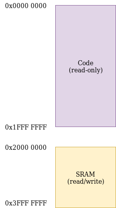
The ARM Cortex M3 (STM32F103RBT6) that I use in this article has 20 Kbytes. See section 2.1 in the STM32F103xB Datasheet. 20 Kbytes equals 20 * 1024 = 20480 (0x5000) bytes. This means that the last valid memory address is 0x2000 0000 + 0x5000 - 0x4 = 0x2000 4FFC.
ARM Cortex M3 boot sequence
The reset vector of STM32F103RBT6 is defined in section 2.3.4 in the STM32F10xxx Programming Manual, it defines the start addresses of exception handlers.
One such exception is system reset whose handler start address is read from 0x0000 0004. This means that the Cortex M3 will execute the code starting at the memory location read from address 0x0000 0004.
The first 7 entries in the reset vector are shown below. The least-significant bits of vector start-addresses must be 1, this indicates that the exception handlers are implemented with Thumb code.
Address        Description
=======        ===========
0x0000 0000    Initial Stack Pointer (SP) value
0x0000 0004    Reset exception
0x0000 0008    NMI
0x0000 000C    Hard fault
0x0000 0010    Memory management fault
0x0000 0014    Bus fault
0x0000 0018    Usage fault
The program is stored as a raw binary file and flashed onto the flash memory of the STM32F103RBT6 starting at address 0x0000 0000. The SRAM memory region, i.e. 0x2000 0000 to 0x2000 4FFC will contain random data when the CPU starts to execute. Any mutable data that the C code assumes is available in a read/write region must be put there by the startup code.
Stack pointer
The first entry in the vector table shown above sets the initial value of the stack pointer. The stack pointer is used by the push and pop instructions at the start and exit of the main() function as shown above.
The stack of the ARM Cortex M3 (STM32F103RBT6) is full descending according to section 2.1.2 in the STM32F10xxx Programming Manual: “This means the stack pointer indicates the last stacked item on the stack memory. When the processor pushes a new item onto the stack, it decrements the stack pointer and then writes the item to the new memory location.”.
We can set the initial stack pointer address to 0x2000 5000 (see ARM Cortex M3 memory map). The stack pointer will then be decremented to 0x2000 4FFC on the first push encountered in the code and store the data there.
C prerequisites
We can compile a number of prerequisities that must be in place in order to execute the assembler code generated from test_program.c.
-
We need to provide a reset vector starting at memory address
0x0000 0000. The reset vector must at the bare minimum contain an initial Stack Pointer (SP) value and an address to start execute code upon system reset. The stack pointer is used by thepushandpopinstructions. -
Make the immutable data in the
.rodatasection available in the read only memory, i.e. address range0x0000 0000to01FFF FFFF. Variableais located in the.rodatasection. -
Make the mutable data in the
.datasection available in the read/write memory, i.e. adress range0x2000 0000to0x200 4FFC. Variablebis located in the.datasection. -
Make the
bsssection available in the read/write memory too. Also make sure all memory in the.bsssection is initialized to zero. Thesumvariable is located in the.bsssection. See BSS in C at Wikipedia.
We want the STM32F103RBT6 memory to look like the image shown below when the assembler code generated from test_program.c starts to execute.
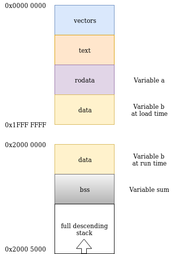
We must use the linker script and also write some C startup code in order to get this.
Linker script
The linker script will tell the linker on what memory locations to put different sections of the code. See chapter 3 about Linker Scripts in the GNU Linker documentation.
We can print the sections available in test_program.o using objdump.
$ arm-none-eabi-objdump -h test_program.o

test_program.o:     file format elf32-littlearm

Sections:
Idx Name          Size      VMA       LMA       File off  Algn
  0 .text         00000020  00000000  00000000  00000034  2**2
                  CONTENTS, ALLOC, LOAD, RELOC, READONLY, CODE
  1 .data         00000004  00000000  00000000  00000054  2**2
                  CONTENTS, ALLOC, LOAD, DATA
  2 .bss          00000004  00000000  00000000  00000058  2**2
                  ALLOC
  3 .rodata       00000004  00000000  00000000  00000058  2**2
                  CONTENTS, ALLOC, LOAD, READONLY, DATA
  4 .debug_info   00000072  00000000  00000000  0000005c  2**0
                  CONTENTS, RELOC, READONLY, DEBUGGING
  5 .debug_abbrev 0000004b  00000000  00000000  000000ce  2**0
                  CONTENTS, READONLY, DEBUGGING
  6 .debug_aranges 00000020  00000000  00000000  00000119  2**0
                  CONTENTS, RELOC, READONLY, DEBUGGING
  7 .debug_line   0000003e  00000000  00000000  00000139  2**0
                  CONTENTS, RELOC, READONLY, DEBUGGING
  8 .debug_str    0000007f  00000000  00000000  00000177  2**0
                  CONTENTS, READONLY, DEBUGGING
  9 .comment      00000032  00000000  00000000  000001f6  2**0
                  CONTENTS, READONLY
 10 .debug_frame  00000030  00000000  00000000  00000228  2**2
                  CONTENTS, RELOC, READONLY, DEBUGGING
 11 .ARM.attributes 00000033  00000000  00000000  00000258  2**0
                  CONTENTS, READONLY
We have all sections available that we want in our final executable besides vectors. The various .debug* sections will be available in the final .elf file for usage by the GDB debugger, but they will not be included in the “raw” binary copied onto the target.
We can write some C code to define a vector table.
#define STACK_TOP 0x20005000
void startup();

unsigned int * myvectors[2]
__attribute__ ((section("vectors")))= {
    (unsigned int *)    STACK_TOP,  // stack pointer
    (unsigned int *)    startup     // code entry point
};
We can now start working on the linker script by adding the vectors and text sections to it. They should be put at the beginning of the read-only memory as shown in the picture above. The way to do this is to first set the so called location pointer, symbolized with a dot ., to 0x0. Followed by an instruction to the linker to create the final .text section from the vectors and .text sections available in the input files to the linker.
SECTIONS
{
    .  = 0x0;         /* From 0x00000000 */

    .text :
    {
        *(vectors)    /* Vector table */
        *(.text)      /* Program code */
    }
}
The .rodata section containing the variable a will also be put in the read-only memory region directly after the .text section.
.rodata :
{
*(.rodata) /* Read only data */
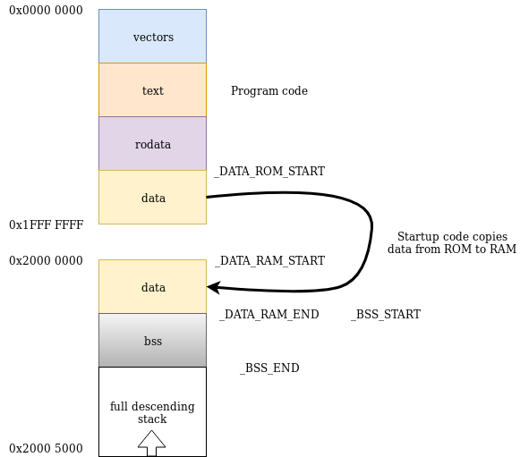
}Next up is the .data section. This section is special compared to the other sections since we want it to be present both in the read-only and read-write parts of the memory.
It should be available in its load time position in the flash memory at system reset. We can put it right after the .rodata section. We create a symbol named _DATA_ROM_START which points to this memory location.
_DATA_ROM_START = .;However the linker script syntax does not allow us inserting the .data section into its position on flash right away. Instead we move the location counter to the start of the SRAM (read/write) memory region. The memory address at the start of this region is stored in symbol _DATA_RAM_START.
.  = 0x20000000;
_DATA_RAM_START = .;
We now place the .data section which contains variable b. The memory address at the end of the .data section is stored in symbol _DATA_RAM_END.
.data :
{
    *(.data)      /* Data memory */
}
_DATA_RAM_END = .;
We have only defined the run time position of the .data section. We need to define the load time address of the .data section. The syntax for doing this in the linker scipt is to use the AT keyword. See section 3.6.8.2 in GNU Linker (ld) manual.
.data : AT(_DATA_ROM_START)
{
    *(.data)      /* Data memory */
}
_DATA_RAM_END = .;
The data belonging to the .data section will not be available in its run time position automatically after system reset. We must write startup code to copy it from its load time position in the flash memory to its run time position in the SRAM memory region.
The .bss section is put right after the .data section. We put start and end addresses in the following symbols:
_BSS_START_BSS_END
_BSS_START = .;   /* Indicates where BSS section starts in RAM */
.bss :
{
    *(.bss)       /* Zero-filled run time allocate data memory */
}
_BSS_END = .;     /* Indicates where BSS section ends in RAM */
The full linker script is shown below.
SECTIONS
{
    .  = 0x0;         /* From 0x00000000 */

    .text :
    {
        *(vectors)    /* Vector table */
        *(.text)      /* Program code */
    }
    .rodata :
    {
        *(.rodata)    /* Read only data */
    }
    _DATA_ROM_START = .;

    .  = 0x20000000;  /* From 0x20000000 */

    _DATA_RAM_START = .;
    .data : AT(_DATA_ROM_START)
    {
        *(.data)      /* Data memory */
    }
    _DATA_RAM_END = .;

    _BSS_START = .;   /* Indicates where BSS section starts in RAM */
    .bss :
    {
        *(.bss)       /* Zero-filled run time allocate data memory */
    }
    _BSS_END = .;     /* Indicates where BSS section ends in RAM */
}
C startup code
The startup code begins by declaring a number of symbols defined in the linker script.
extern unsigned int _DATA_ROM_START;
extern unsigned int _DATA_RAM_START;
extern unsigned int _DATA_RAM_END;
extern unsigned int _BSS_START;
extern unsigned int _BSS_END;
After that we define a vector table as already shown above. We also have to forward declare the startup function defined below since we need to reference it in the vector table.
#define STACK_TOP 0x20005000
void startup();

unsigned int * myvectors[2]
__attribute__ ((section("vectors")))= {
    (unsigned int *)    STACK_TOP,  // stack pointer
    (unsigned int *)    startup     // code entry point
};
We now write a function named startup() with the following responsiblities:
- Copy data belonging to the
.datasection from its load time position on flash (ROM) to its run time position in SRAM. - Initialize data in the
.bsssection to zeros. - Call the
main()function defined intest_program.c.
We need to make a forward declaration of the main function since we reference it at the end of the startup function.
void main();

void startup()
{
    /* Copy data belonging to the `.data` section from its
     * load time position on flash (ROM) to its run time position
     * in SRAM.
     */
    unsigned int * data_rom_start_p = &_DATA_ROM_START;
    unsigned int * data_ram_start_p = &_DATA_RAM_START;
    unsigned int * data_ram_end_p = &_DATA_RAM_END;

    while(data_ram_start_p != data_ram_end_p)
    {
        *data_ram_start_p = *data_rom_start_p;
        data_ram_start_p++;
        data_rom_start_p++;
    }

    /* Initialize data in the `.bss` section to zeros.
     */
    unsigned int * bss_start_p = &_BSS_START;
    unsigned int * bss_end_p = &_BSS_END;

    while(bss_start_p != bss_end_p)
    {
        *bss_start_p = 0;
        bss_start_p++;
    }


    /* Call the `main()` function defined in `test_program.c`.
     */
    main();
}
The full C startup code is shown below.
extern unsigned int _DATA_ROM_START;
extern unsigned int _DATA_RAM_START;
extern unsigned int _DATA_RAM_END;
extern unsigned int _BSS_START;
extern unsigned int _BSS_END;

#define STACK_TOP 0x20005000
void startup();

unsigned int * myvectors[2]
__attribute__ ((section("vectors")))= {
    (unsigned int *)    STACK_TOP,  // stack pointer
    (unsigned int *)    startup     // code entry point
};

void main();

void startup()
{
    /* Copy data belonging to the `.data` section from its
     * load time position on flash (ROM) to its run time position
     * in SRAM.
     */
    unsigned int * data_rom_start_p = &_DATA_ROM_START;
    unsigned int * data_ram_start_p = &_DATA_RAM_START;
    unsigned int * data_ram_end_p = &_DATA_RAM_END;

    while(data_ram_start_p != data_ram_end_p)
    {
        *data_ram_start_p = *data_rom_start_p;
        data_ram_start_p++;
        data_rom_start_p++;
    }

    /* Initialize data in the `.bss` section to zeros.
     */
    unsigned int * bss_start_p = &_BSS_START;
    unsigned int * bss_end_p = &_BSS_END;

    while(bss_start_p != bss_end_p)
    {
        *bss_start_p = 0;
        bss_start_p++;
    }


    /* Call the `main()` function defined in `test_program.c`.
     */
    main();
}
Building
We need to perform a couple of steps to build test_program.c together with startup.c using our own linker script.
Compile the C files into object files using gcc. We use no optimization via the -O0 flag (section 3.10 in the gcc documenation) in order to make the step command in the GDB debugger work as expected. We use the -g flag to produce debugging information, see 3.9 in the gcc documenation:
arm-none-eabi-gcc -O0 -c -g -mcpu=cortex-m3 -mthumb -o test_program.o test_program.c
arm-none-eabi-gcc -O0 -c -g -mcpu=cortex-m3 -mthumb -o startup.o startup.c
Link the object files according to the rules in our linker script named stm32.ld using GNU linker ld.
arm-none-eabi-ld -Tstm32.ld -o test_program.elf startup.o test_program.oUse objcopy to convert the .elf file from the linker into a “raw” binary. The “raw” binary is what we will run on the target while we will feed the elf file into the GDB debugger since it contains debugging information.
arm-none-eabi-objcopy -O binary test_program.elf test_program.binWe can inspect the sections in .test_program.elf with objdump as we did with test_program.o above.
$ arm-none-eabi-objdump -h test_program.elf

test_program.elf:     file format elf32-littlearm

Sections:
Idx Name          Size      VMA       LMA       File off  Algn
  0 .text         00000098  00000000  00000000  00010000  2**2
                  CONTENTS, ALLOC, LOAD, READONLY, CODE
  1 .rodata       00000004  00000098  00000098  00010098  2**2
                  CONTENTS, ALLOC, LOAD, READONLY, DATA
  2 .data         00000004  20000000  0000009c  00020000  2**2
                  CONTENTS, ALLOC, LOAD, DATA
  3 .bss          00000004  20000004  000000a0  00020004  2**2
                  ALLOC
  4 .debug_info   0000015c  00000000  00000000  00020004  2**0
                  CONTENTS, READONLY, DEBUGGING
  5 .debug_abbrev 000000cc  00000000  00000000  00020160  2**0
                  CONTENTS, READONLY, DEBUGGING
  6 .debug_aranges 00000040  00000000  00000000  0002022c  2**0
                  CONTENTS, READONLY, DEBUGGING
  7 .debug_line   00000089  00000000  00000000  0002026c  2**0
                  CONTENTS, READONLY, DEBUGGING
  8 .debug_str    0000013a  00000000  00000000  000202f5  2**0
                  CONTENTS, READONLY, DEBUGGING
  9 .comment      00000031  00000000  00000000  0002042f  2**0
                  CONTENTS, READONLY
 10 .ARM.attributes 00000033  00000000  00000000  00020460  2**0
                  CONTENTS, READONLY
 11 .debug_frame  00000064  00000000  00000000  00020494  2**2
                  CONTENTS, READONLY, DEBUGGING
Each section has a virtual memory address (VMA) and a load memory address (LMA). Section 3.1 in the GNU Linker documentation explains VMA and LMA:
Every loadable or allocatable output section has two addresses. The first is the VMA, or virtual memory address. This is the address the section will have when the output file is run. The second is the LMA, or load memory address. This is the address at which the section will be loaded. In most cases the two addresses will be the same. An example of when they might be different is when a data section is loaded into ROM, and then copied into RAM when the program starts up (this technique is often used to initialize global variables in a ROM based system). In this case the ROM address would be the LMA, and the RAM address would be the VMA.
The .data section has different VMA and LMA as expected. VMA is 0x20000000, i.e. at the beginning of the SRAM. LMA is 0x9c which is right after the .rodata section in ROM.
Idx Name          Size      VMA       LMA       File off  Algn
  2 .data         00000004  20000000  0000009c  00020000  2**2
                  CONTENTS, ALLOC, LOAD, DATA
The sections also have flags associated with them, e.g. CODE, READONLY and DATA. Some of the flags are self explaining, e.g. the .text section contains executable CODE, whereas other are harder to understand.
Figure 4-11 of Chapter 4 in System V Application Binary Interface explains a subset of these flags although using different names.
There is also a relevant conversation on stack overflow:
CODE means that the section contains executable code; it is indicated by the SHF_EXECINSTR flag in the section header
DATA means that the section is not executable but is writable, indicated by the presence of the SHF_WRITE flag
READONLY means that the section is neither executable nor writtable and should be placed in read-only memory pages
ALLOC means that the section occupies memory, e.g. memory pages are actually allocated to hold the section content when a process is created, indicated by the SHF_ALLOC flag. Some sections, e.g. those containing debug information, are not read into memory during normal program execution and are not marked as ALLOC to save memory.
We can inspect the symbols with corresponding memory addresses in test_program.elf using arm-none-eabi-nm:
$ arm-none-eabi-nm --numeric-sort test_program.elf
00000000 T myvectors
00000008 T startup
00000078 T main
00000098 r a
0000009c R _DATA_ROM_START
20000000 d b
20000000 D _DATA_RAM_START
20000004 D _BSS_START
20000004 D _DATA_RAM_END
20000004 b sum
20000008 B _BSS_END
We will use the memory addresses of a, b and sum to verify that our program has run correctly.
Running
OpenOCD server
Start the openocd server in one command window. See the previous post Using OpenOCD to flash ARM Cortex M3.
$ openocd -f openocd.cfgFlashing
We flash test_program.bin onto the ARM Cortex M3 using OpenOcd.
Connect to the openocd server using telnet in another command window
$ telnet localhost 4444Halt execution of target in case it is running
reset haltErase content on flash
stm32f1x mass_erase 0Flash test_program.bin
flash write_bank 0 test_program.bin 0Run program but halt directly so that we can control the execution via the debugger (gdb)
reset haltDebugging
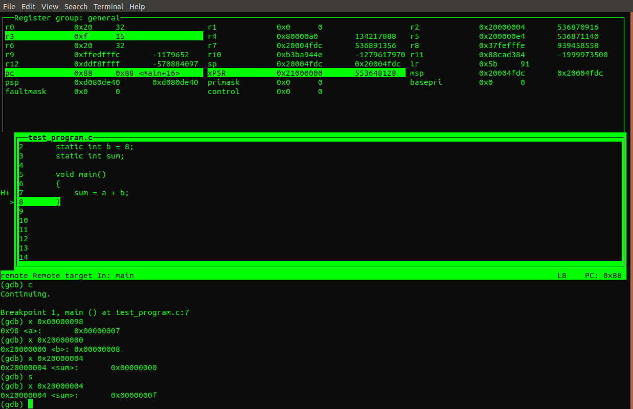
Run gdb using our test program and connect to the openocd server on port 3333. We use the GDB TUI (Text User Interface) as described in Use GDB on an ARM assembly program.
gdb-multiarch -tui --eval-command="target remote localhost:3333" test_program.elf Display register values in GDB
(gdb) layout regs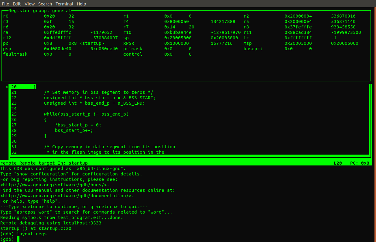
Set a break point at the beginning of the main() function in test_program.c.
(gdb) hbreak main
Hardware assisted breakpoint 1 at 0x7c: file test_program.c, line 7.
(gdb) c
Continuing.

Breakpoint 1, main () at test_program.c:7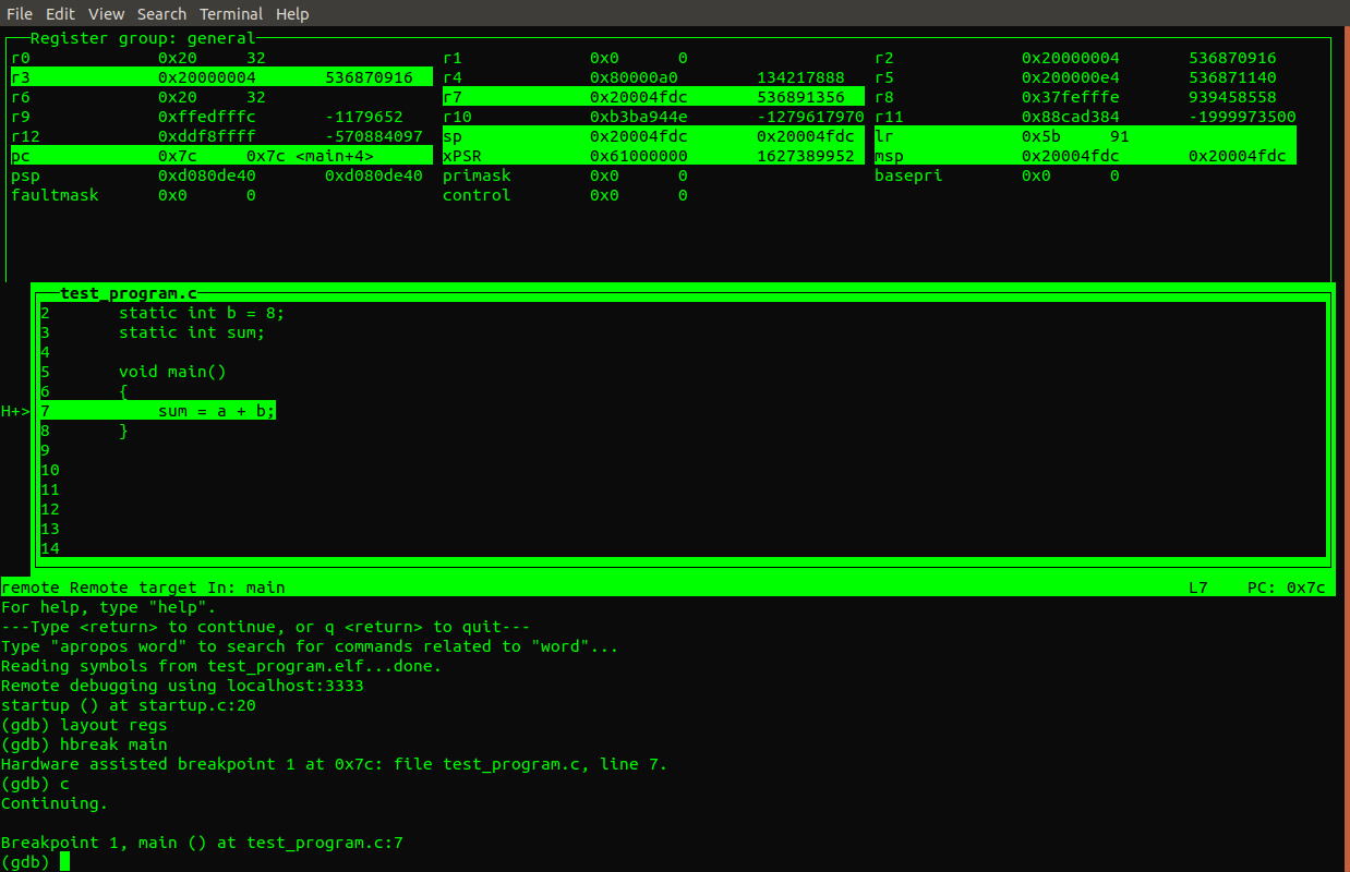
Inspect the values of a, b and sum before executing sum = a + b.
(gdb) x 0x00000098
0x98 <a>:       0x00000007
(gdb) x 0x20000000
0x20000000 <b>: 0x00000008
(gdb) x 0x20000004
0x20000004 <sum>:       0x00000000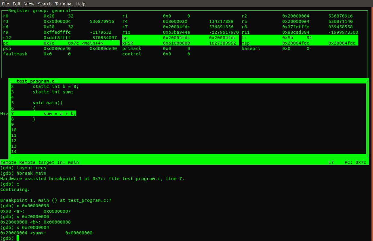
Execute sum = a + b using the GDB step command (section 5.2 in GDB manual) and inspect sum variable again.
(gdb) s
(gdb) x 0x20000004
0x20000004 <sum>:       0x0000000f
The sum variable now equals 0x0F (15) which is correct.